|
Decade 260 Series Process Monitoring |
|
The high-tech process monitoring system for
assembly operations and product testing. The 260 Series provides the facility to measure,
analyze and then determine a pass or fail result during component assembly or test processes. By measuring process variables such as Force and Position it is possible to determine the quality of assembled components - providing a Poke-Yoke 100% testing facility for every component made. |
- The 260 can monitor up to eight separate Test Processes on one machine.
- Tool based system stores all process monitoring parameters in tool database. A tool can also be externally selected by controlling PLC.
- The Test Sequencer function can package individual test processes in multi-stage machines to give one overall result for each machine cycle.
- Each test process test can have up to four check-regions each with separate pass/fail criteria.
- A Fault Log provides historical failure information.
- Statistical Functions generate Xbar, Range, Cpk and sigma results from process results.
- Large 10.4” TFT colour touch screen for clear display of process data and an intuitive interface.
- Configurable I/O channels, and easy wiring to controlling PLC.
- Data output facility to get sampled data, SPC data and Fault Log data into spreadsheets.
Typical Applications :
- General component insertion.
- PDI Test Machines.
- Bearing and Oil Seal insertion.
- Gear and Pinion pressing on to shafts.
- Valve Guide / Valve Seat insertion in to cylinder head.
- Cylinder Liner insertion.
- Core Plug insertion.
- Wheel Stud insertion.
- Spin riveting, Rivet setting.
- Pressure testing.
- Staking and Swaging operations.
- Single and multi point Bush insertions.
- Push-Out testing.
- Effort checking in sub-assemblies.
- Deflection testing.
- Torque, Friction testing.
| Main Screen | |||||||||
 |
|||||||||
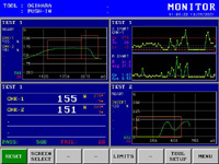
Monitor Screen
|
|||||||||
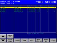
| The Tool Database |
The Tool Database stores all the process setup parameters for the 260 unit. Typically the tool database can store up to 200 tool setups with the standard memory.
You can create different tools to accommodate different assembly processes or machine-tools.
Tool setup can also be automatically loaded via external BCD coded input signals from a PLC of machine control. |
||||||||
 |
|||||||||
| Intuitive Setup Screens | |||||||||
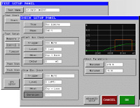 |
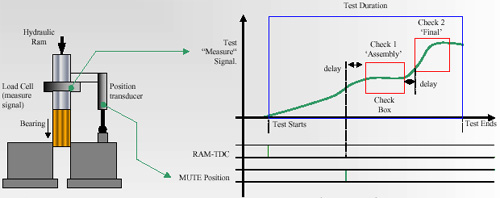
Setting up new process tests and checks is quick and simple. The 260 units is designed to be extremely flexible but yet simple to understand. A single screen controls all of the process test parameters, and check setup screens control how the process is measured. When setting up process checks you can see a graph of the measurement and control signals, and check boxes are clearly displayed on the graphs. |
||||||||
| Process Monitoring | |||||||||
The 260 works by measuring process values such as Force,Pressure or Torque from a transducer situated in the tooling of the machine. Each one of these measurement signals is processed in a ‘Test’. As a part is pushed into a another part, or a torque is applied, or a pressure is built up the 260 is sampling these values into its memory. Then based on other controlling signals ‘Checks’ are made during the ‘Test’ that compare the measured values against pre-set process limits, and if the measured signal falls outside these set limits the whole Test is flagged up as failed. |
|||||||||
 |
|||||||||
|
|||||||||
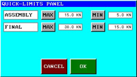
| Controlling Process Limits | Controlling the pass and fail limit parameters for the test is quick and easy. One key brings up a screen that shows just the pass / fail limits for the chosen test. These limits, and all other setup parameters, can be protected by a versatile password system. Users can have their own PIN number identity and access level assigned to them. | ||||||||
 |
|||||||||
| I/O Connections to Controlling PLC | |||||||||
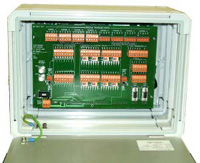 |
Opening the rear of the 260 enclosure provides access to the digital I/O, serial ports, power and transducer connections. The digital I/O signals are all is 24v DC, inputs can be selected as NPN/PNP and outputs are supplied as PNP (source) as standard.Each I/O channel has a LED indicator and connections are made through removable plugs. There are 32 digital input channels and 16 digital outputs. The digital I/O can be electrically isolated and fed from an external supply. | ||||||||
| Analogue transducers are also wired into removable plugs. A 24v DC 3A power supply is required. |
|||||||||
| Specifications : | |||||||||
 |
|||||||||
|
|||||||||